One of the major role of Physical layer is to transfer the data in form of signals through a transmission medium. It doesn’t matter what data you are sending, it can be text, audio, image, video etc. everything is transferred in form of signals. This happens because a data cannot be send as it is over a transmission medium, it must be converted to a form that is acceptable by the transmission media, signals are what a transmission medium carry. In this guide, we will discuss data and signals.
Analog and Digital
Both the data and the signal can be represented in form of analog and digital.
Analog and Digital Data:
Analog data is continuous data that keeps changing over time, for example in an analog watch, the hour, minute and second hands keep moving so you infer the time by looking at it, it keeps changing. On the other hand digital watch shows you discrete data such as 12:20 AM, 5:30 PM etc. at a particular moment of time.
Analog and Digital Signals:
Similar to data, a signal can be analog or digital. An analog signal can have infinite number of values in a given range, on the other hand a digital signal has limited number of values in a given range. The following digram shows analog and digital signals.
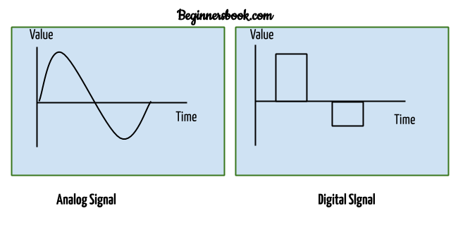
1. Analog Signals
An analog signal can be be categorized as simple or composite.
1.1 Simple Analog signal
A simple analog signal can be represented in form of sine wave. A sine wave is shown in the above diagram.
A simple analog signal is smooth, consistent and continuous. As you can see in the diagram above that a arc above the time axis is followed by the similar arc below the time axis and so on.
Parameters of simple Analog signal – Sine wave
There are three parameters that defines a sine wave – peak amplitude, frequency and phase.
Peak amplitude: Absolute value of highest intensity of sine wave.
Frequency and Period: Period is the amount of time a signal takes to complete one cycle, it is denoted by T. Frequency refers to the number of cycles in 1 second, it is denoted by f. They are inversely proportional to each other which means f = 1/T.
Phase: Phase refers to the position of sine wave relative to the time 0. For example if the sine wave is at its highest intensity at the time zero then the phase value for this sine wave is 90 degrees. Phase is measured in degrees or radians.
1.2 Composite Analog signal
Unlike sine wave which is smooth and consistent, composite analog signals or waves are not smooth and consistent, which means an arc above the time axis doesn’t necessarily followed by arc below the time axis. You can imagine them as a group of sine waves with different frequency, amplitude and period.
Bandwidth: The range of frequencies in a composite signal is called bandwidth. For example if a composite signal contains waves with the frequencies ranging from 2000 to 4000 then you can say that the bandwidth of this composite signal is 4000-2000 = 2000Hz. Bandwidth is measured in Hz.
2. Digital Signals
Similar to analog signals, data can be transmitted in form of digital signals. For example a data that is converted it into a machine language (combination of 0s and 1s) such as 1001 can be represented in form digital signals. 1 represents high voltage and 0 represents low voltage.
Bit Rate: A bit rate is measured as bits per second, it represents the number of 1s send in 1 second.
Bit Length: A bit length is the distance a bit occupies on the transmission medium.
Now that you are familiar with analog and digital signals, it’s time time to cover digital transmission which we will discuss in the next chapter.
Ekta Patel says
This guide is very helpful for learning COMPUTER NETWORK BASICS in details. THANK YOU FOR THIS.